How to nail hydraulic logic element leakage |
|
One of our members wrote to me recently with the following question:
"In one of our applications we are using NG 40 slip-in cartridge valves (sleeve, poppet and logic cover). With the valve closed and the inlet port pressurized to 315 bar, we are seeing a leakage from the outlet port in the order of half a liter per minute. Is this level of leakage acceptable?"
The first thing to consider is whether the logic element has been configured for leakless operation. If the direction of flow is from A to B this is referred to as base flow. If flow is from B to A this is know as annulus flow (see figure 1). A logic element can be configured for flow in either or both directions.
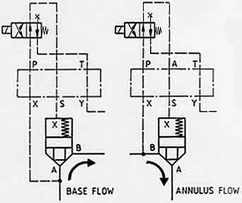
Figure 1. Logic element base and annulus flow configurations (Industrial Hydraulic Control).
To establish whether a logic element is configured for zero leakage, it is necessary to consider the direction of pressure drop across the poppet when it is closed. Consider a logic element configured for check valve function in both base and annulus flow directions. When configured as a check valve for base flow (A to B) see figure 2, the direction of pressure drop across the poppet when it is closed is from B to A. In this configuration the logic element is leakless.

Figure 2. Logic element; check valve function; base flow (Industrial Hydraulic Control).
When configured as a check valve for annulus flow (B to A) see figure 3, the direction of pressure drop across the poppet when it is closed is from A to B. In this configuration the clearance between the poppet and its sleeve results in leakage from A to B. The magnitude of this leakage may increase over time as a result of wear between the poppet and sleeve.

Figure 3. Logic element; check valve function; annulus flow (Industrial Hydraulic Control).
Assuming our reader's logic elements have been configured for leakless operation, other possible explanations for the leakage include:
- damage to the poppet and/or its seat
- degradation or damage to the elastomeric seal around the base of the sleeve
- incorrect machining tolerance in the logic housing
In this, and all other troubleshooting situations, the first place to look for guidance is the machine's circuit diagram and your reference library. From there on, it is a logically process of elimination.
Related articles:
Hydraulic troubleshooting basics |
If you enjoyed this article, you'll love Brendan Casey's Inside Hydraulics newsletter. It gives you real-life, how-to-do-it, nuts-and-bolts, hydraulics know-how -- information you can use today. Here's what a few members have said about it:
Can't Put It Down
?I get e-mails like this all the time. I never find time to read them. I decided to read Issue #30 and I couldn't put it down. I'll make time from now on.?
Richard A. Shade, CFPS, Project Engineer (Hydraulic Design), JLG Industries Inc.
So Valuable It Earned Me A Raise
?The knowledge I've gained from this newsletter has been so valuable it has earned me a raise!?
Jack Bergstrom, Heavy Equipment Mechanic, Sharpe Equipment Inc.
Love It - Keep Them Coming
?I just love this newsletter. As a Hydraulics Instructor for Eaton, I make copies and distribute them to my students as I address various topics. Please keep 'em coming.?
Michael S Lawrence, Hydraulics Instructor, Eaton Hydraulics Inc.
To get your FREE subscription ($149 value), simply type your first name and primary email address into the form below and hit 'SUBSCRIBE NOW!'
|
This is a private mailing list that will NEVER
be shared for any reason. |
Copyright © 2000 - 2013 Brendan Casey; HydraulicSupermarket.com