

A millwright recently completed a 5-day basic hydraulics training. He plans to use his recently acquired hydraulics knowledge to check and set the relief valves in the circuit shown below, using a hand pump. Valves 04 and 06 are both relief valves (no external drains are shown). The rear section of the tandem pump 01 provides two pilot pressures: Pp1 and Pp2. The front section of the tandem pump is cooling/flushing. Heat exchanger 07 and filter 08 have bypass valves, as shown. Pump 01 is driven by an electric motor and filters 02 and 08 have delta-P switches. Filter 02’s delta-P switch shuts down the pump.
How would you advise the millwright to proceed with his hand pump?
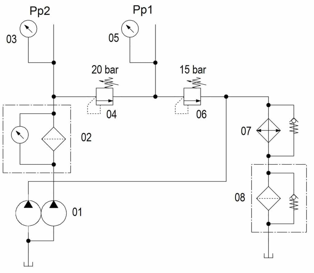
Hydraulic pilot circuit
If you’re not yet ready for the answer, stop reading here.
ANSWER: The specified setting values of pressure controls shown on drawings and in the machine manual are typically not their cracking or start of control pressure, but rather maximum pressure at design flow rate with the system running at operating temperature. In others words, the specified pressure setting is a maximum value taking into account all system and component dynamic effects. These effects include: design flow rate, hydraulic resistance and fluid temperature and viscosity. In the case of a direct acting relief valve these effects also include: the valve’s pressure over ride and the pressure acting on its spring chamber. A hand pump does not and cannot replicate any of these system dynamic effects. It is therefore practically impossible to set any pressure control accurately using a hand pump, unless a cracking pressure is specified and the valve is externally drained. In the case of a direct acting relief valve, it means if it is set to its specified pressure using a hand pump, the resulting pressure setting will almost certainly be TOO HIGH!
So the advice to the millwright is simple: “Do NOT use a hand pump”. In this circuit, relief valve 06 must be set to 15 bar on gauge 05 while operating pressure drop across 07 and 08 is acting on its spring chamber (pump running). Relief valve 04 is then set to 20 bar so that the pressure showing on gauge 03 is 35 bar. These set pilot pressures will vary with the (minor in this case) variation in pressure drop across 07 and 08. If this were an issue, 04 and 06 should be sequence valves, in which case 04 would be set at 35 bar (not 20 bar). And note that most pressure controls are affected by downstream pressure unless they have an external drain.
Key takeaway: It is practically impossible to set any pressure control accurately using a hand pump. And in the case of a direct acting relief valve, it means if it is set to its specified pressure using a hand pump, the resulting pressure setting will almost certainly be TOO HIGH! In other words, setting a pressure control using a hand pump can be a costly mistake. And to discover 6 other costly mistakes you want to be sure to avoid with your hydraulic equipment, get “Six Costly Mistakes Most Hydraulics Users Make… And How You Can Avoid Them!” available for FREE download here.